
Engineered Pneumatic Boosters & Precision Modules
High-ratio gas-liquid boosters, explosion-safe air amplificators, and custom die tool components designed for continuous industrial operation under rigorous cyclic duty.
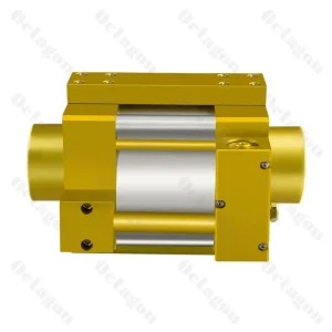
High-Quality China Suppliers: Octagon SWB-100S & SWB-100D Series Pumps from Factory for Reliable Industrial Applications Factories, Exporters
Explore Technical Specs
CE Certification Octagon SWB-100S & SWB-100D Pumps - High-Performance Gas Pumps from China Suppliers & Factory Manufacturers, Product
Explore Technical Specs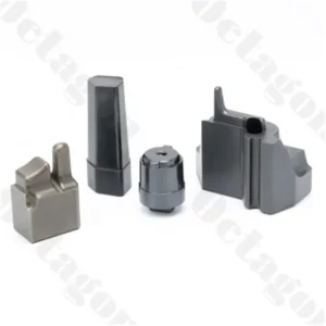
OEM China Die Casting Mold Parts Processing - Quality Suppliers & Factory for Customized Components Suppliers, Exporters
Explore Technical Specs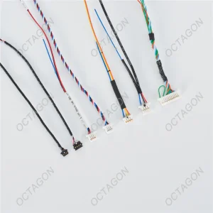
ODM Octagon Speaker Wire Harness - Premium Audio Solutions from China Suppliers and Factory Supplier, Factories
Explore Technical Specs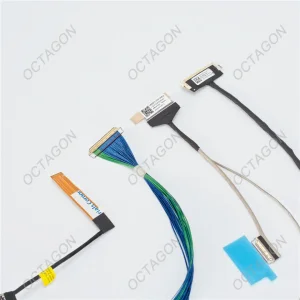
Custom High-Definition Screen Connection Cable harness Manufacturer, Exporters
Explore Technical Specs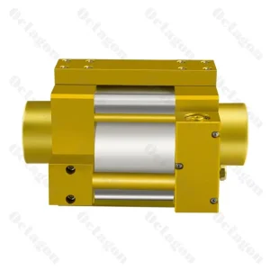
CE Certification High-Performance Gas-Liquid Booster Pump Octagon SWB - 125D from China Suppliers and Factory Factory, Exporter
Explore Technical Specs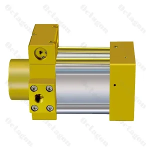
ODM China Octagon SWB-80S Series Gas-Liquid Booster Pump - Efficient Solutions from Top Suppliers and Factory Supplier, Exporters
Explore Technical Specs
High-Quality Octagon SWB-80S Series Gas-Liquid Booster Pump Manufacturer, Exporter
Explore Technical SpecsThe Fundamentals of Differential Area Pneumatic Pressure Intensification
Pneumatic pressure pumps (also categorized as air-driven liquid pumps, gas boosters, or pneumatic intensifiers) operate upon the foundational principles of hydrostatic equilibrium defined by Pascal’s Law. Unlike conventional rotary or centrifugal pumps that rely on continuous electric motor drives and shaft dynamic seals, pneumatic booster pumps utilize a reciprocating differential-area piston mechanism.
By applying standard shop compressed air (typically 3 to 8 bar / 45 to 116 psi) across a large-diameter drive air piston, mechanical thrust is transferred directly via an interconnected push rod to a significantly smaller high-pressure plunger. The resultant output pressure is inversely proportional to the surface area ratio:
Poutlet = (Adrive / Ahigh_pressure) × Pdrive + PprechargeWhere the intensification ratio
i = Adrive / Ahigh_pressure can vary from 2:1 up to 100:1 or higher, enabling modest 6-bar plant pneumatic lines to generate fluid hydraulic or pneumatic forces exceeding 600 bar (8,700 psi) without consuming electrical energy.
Because the reciprocating drive alternates via an unbalanced pneumatic spool valve or pilot-operated directional shuttle mechanism, the pump automatically stalls when the downstream process pressure reaches force equilibrium with the pneumatic drive force. Once stalled, the system consumes zero compressed air while maintaining precise holding pressure indefinitely without thermal generation, fluid degradation, or reliance on electric bypass circuits.
Thermodynamic & Safety Edge
In hazardous classified zones (ATEX Zone 1/21, Class I Div 1), electrical motors and servo hydraulic power packs introduce substantial explosion hazards and require heavy explosion-proof enclosures. Pneumatic pressure pumps provide an inherently safe, explosion-proof fluid power platform devoid of spark risks, electrical windings, or heat dissipation concerns.
Technological Trajectories in Pneumatic Intensification
Examining the structural evolution from conventional air boosters to intelligent, zero-emission pneumatic-hydraulic intensification stations engineered for Industry 4.0 automation.
Dry-Running Tribological Seal Matrices
Traditional pneumatic pumps depended upon inline lubricators, introducing oil aerosol contamination into compressed air exhaust and fluid pathways. Modern high-tier designs utilize carbon-fiber reinforced PTFE, virgin PEEK back-up rings, and ultra-high-molecular-weight polyethylene (UHMW-PE) lip seals capable of dry operation across millions of cycles without lubrication, essential for cleanroom medical and semiconductor tooling.
Electro-Pneumatic Closed-Loop HMI Control
The convergence of pneumatic mechanics with microprocessor logic enables digital high-pressure control cabinets. By incorporating dynamic pressure transducers, micro-second fast-switching pilot solenoid valves, and PLC touch-screens, operators can govern dual-stage multi-pressure profiles, cycle timing down to ±5 milliseconds, and automated stall-detection diagnostics.
Integrated Dual-Acting High-Displacement Geometry
Single-acting booster pumps suffer from fluid delivery intermittence during the intake stroke. The engineering transition toward double-acting gas-liquid models (e.g., SWB-100D and SWB-125D series) ensures continuous hydraulic delivery on both advance and retraction strokes, cutting cycle downtime by 48% and mitigating fluid pressure pulsation in high-pressure testing fixtures.
Global Sourcing Framework: Selecting Industrial Booster Pumps
Procurement and manufacturing teams must evaluate pneumatic intensifiers beyond upfront purchase cost. A rigorous engineering assessment encompasses air consumption efficiency, lifecycle maintenance, and seal replacement intervals.
| Evaluation Parameter | Pneumatic Intensifier Pump (SWB/SWP) | Electric Motor Hydraulic Power Unit (HPU) | Direct Gas Compressor / Piston Station |
|---|---|---|---|
| Primary Drive Energy | Compressed Air (3-8 bar) | Three-Phase AC Electricity (380V/480V) | Electric Motor / Crankshaft Drive |
| Pressure Stall Efficiency | Zero Energy Consumption (Stalls on demand) | High Bypass Losses / Continuous Idling Load | Recirculation Bypass / Frequent Motor Start-Stop |
| Hazardous Zone Safety | ATEX Safe (Zero spark, non-electric) | Requires costly explosion-proof containment | Heavy flameproof containment enclosures |
| Thermal Signature | Self-cooling via expanding drive exhaust | Requires external heat exchangers / chillers | High internal heat of gas compression |
| Volumetric Envelope | Ultra-compact footprint, inline mounting | Large reservoir tank, motor, manifold block | Substantial structural baseframe required |
| Mean Time to Overhaul (MTBF) | > 5,000,000 Cycles (Cartridge seal rebuilds) | 10,000 Operating Hours (Motor/Pump wear) | 3,000 - 5,000 Operating Hours (Valves/Rings) |
Total Life-Cycle Operating Costs
Because pneumatic intensifiers instantly cease air consumption once downstream target pressure is reached, holding pressure during curing, clamping, or burst testing yields near-zero energy consumption. In continuous pressure-holding mold applications, plants report up to 72% electrical energy reduction compared to running continuous motor-driven bypass pumps.
Cartridge Seal Field Serviceability
Downtime in automotive stamping and die-casting lines incurs exorbitant hourly costs. Leading manufacturers mandate modular cartridge seal arrangements. Plungers, dynamic high-pressure packings, and check-valve discs can be disassembled and replaced within 20 minutes without dismounting fluid line plumbing.
Supply Chain Redundancy & Traceability
Global procurement directives prioritize raw material origin, mill test certificates (MTRs), and standard metric/BSPP/NPT port compliance. Full lot traceability on high-pressure cylinder barrels (17-4PH or 316L stainless) ensures long-term operational integrity and compliance with plant safety audits.
Turnkey Solutions Across Demanding Sectors
From micro-precision electronic degating to extreme hydrostatic pressure containment, pneumatic intensifiers provide deterministic fluid power across core manufacturing domains.
In-Mold Degating & Trim
In automated injection molding, pneumatic-hydraulic boosters generate forces from 1,000 to 7,000 kgf within compact control cabinets. Cutting gates while the mold remains clamped eliminates manual trimming, prevents gate blush, and shortens cycle times in automotive lenses and medical housings.
Pressure Proof & Burst Testing
Manufacturers of hoses, accumulators, common-rail diesel injectors, and aerospace titanium tubing deploy air-driven pumps for cyclical hydrostatic proof tests and destructive burst validation up to 4,000 bar using DI water, glycol, or mineral hydraulic oil.
Gas Assist & Bottle Charging
Pneumatic gas boosters scavenge industrial nitrogen, helium, or argon bottles down to residual pressures of 15 bar and boost the gas to 350+ bar for nitrogen laser cutting assist, gas-assisted plastic molding, and accumulator pre-charging stations.
Automotive Tooling & Clamping
High-tonnage stamping dies and quick die-change (QDC) clamps mandate fail-safe hydraulic holding pressure during press operations. Air boosters maintain intense hydraulic clamping pressures indefinitely, eliminating hydraulic power unit creep and electrical downtime.
Sub-Micron Machining Tolerances & Advanced Metallurgy
Fluid leakage across high-pressure reciprocating plungers is governed by the cubic relationship of the annular clearance gap. A microscopic variation in diametral clearance drastically accelerates high-pressure bypass leakage. To overcome this fundamental mechanical hurdle, Octagon enforces precision CNC grinding and cylindrical lapping processes that achieve dimensional tolerances to ±0.002 mm (±2 microns).
High-pressure plungers undergo cryogenic hardening treatments followed by superfinishing or hard-chrome/DLC (Diamond-Like Carbon) thin-film coating, yielding mirror surface roughness values between Ra 0.05 and Ra 0.2 μm. This minimizes dynamic friction coefficients against multi-lip dynamic packing seals, drastically suppressing micro-chattering and seal degradation during extended high-cycle duty.
- Fluid Plunger: 17-4PH Precipitation Hardened Stainless Steel / Nitrided Tool Steel (HRC 58-62)
- Pressure Barrel: High-tensile forged 316L or 42CrMo4 alloy steel with internal barrel roller burnishing
- Drive Air Cylinder: Hard-anodized 6061-T6 / 7075 aluminum alloy with Teflon-impregnated inner bores
- Check Valves: Ceramic or Tungsten Carbide balls with precision-machined 316L seats for zero drip backflow
Full-Process Quality Inspection Architecture
Every pneumatic pump undergoes multi-stage verification adhering to ISO 9001 quality workflows:
- CMM Coordinate Metrology: Zeiss 3D coordinate checking of valve bores and plunger concentricity.
- Dynamic Stall Verification: 24-hour continuous holding pressure test verifying zero pressure decay.
- Low-Pressure Pilot Response: Validating that directional spool valves shift smoothly at low 1.5 bar drive pressure without binding.
- Helium Mass Spectrometry: Optional cleanroom gas test confirming leak rates below 10-6 mbar·L/s.
International Certifications & Regulatory Assurance
Deploying pressurized machinery across European, North American, and Asian industrial markets mandates rigorous adherence to international safety directives and documentation integrity.
European Directives (CE, PED, ATEX)
Octagon pneumatic pressure pumps conform to the European Machinery Directive 2006/42/EC and Pressure Equipment Directive (PED 2014/68/EU). Certified mechanical ATEX construction (EN ISO 80079-36/37) ensures spark-free installation inside explosive dust and solvent vapor zones.
North American ASME & CRN Readiness
For installations in the USA and Canada, fluid pressurized chambers and high-pressure accumulator cylinders can be engineered to ASME Boiler and Pressure Vessel Code Section VIII Division 1 guidelines, backed by Canadian Registration Numbers (CRN) for inter-provincial clearance.
RoHS, REACH & Cleanroom Compatibility
All fluoropolymer seals, lubricants, and metal platings comply with EU RoHS 3 and REACH SVHC restrictions. Optional silicone-free and fluorosilicone-free builds guarantee compatibility with automotive electro-deposition paint facilities and semiconductor vacuum environments.
Technology Roadmap: Edge IoT & Predictive Fluid Maintenance
As smart manufacturing frameworks expand across injection molding and hydroforming sectors, pneumatic pressure pumps are transitioning from passive mechanical components to telemetry-enabled fluid nodes. The upcoming generation of Octagon pneumatic systems integrates non-intrusive sensory architectures directly into the cylinder tie rods and pilot shuttle housings.
By monitoring high-frequency pressure wave pulsation, cycle repetition frequency, and air exhaust acoustic profiles via embedded MEMS sensors, the system detects micro-seal wear or check-valve contamination dozens of operating hours before actual pressure loss occurs. This predictive data transmits via IO-Link or Modbus TCP to factory supervisory systems, eliminating unexpected downtime.
- Ultra-High-Pressure Hydrogen Booster Systems: Compression up to 1,050 bar (15,200 psi) for hydrogen refueling and fuel-cell test benches with embrittlement-resistant metallurgy.
- Zero-Friction Ceramic Plungers: Advanced zirconia-toughened alumina (ZTA) reciprocating elements delivering zero metallic ion contamination.
- Adaptive Cycle Throttle Valves: Integrated proportional flow control optimizing compressed air consumption based on real-time fluid backpressure.
Engineering Customization Protocol (OEM / ODM)
Octagon provides full custom engineering for specialized industrial requirements. When requesting bespoke pneumatic pump packages, customers can specify:
Air Boosters, Tooling Components & Interconnect Assemblies
Industrial pneumatic air booster pumps, high-precision stamping die elements, and mission-critical wire harness assemblies engineered for equipment cabinets and harsh industrial environments.
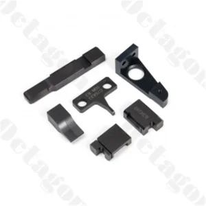
CE Certification Precision Stamping Die Components from China: Reliable Suppliers for Your Factory Needs Factory, Factories
Explore Technical Specs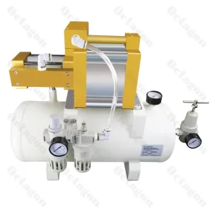
OEM China Octagon SWP-7.5-G Air Booster Pump Factory - Efficient Pneumatic Pressure Enhancement from Reliable Suppliers Manufacturer, Exporter
Explore Technical Specs
CE Certification High-Definition Screen Connection Cable Harness from China Suppliers - Reliable Factory Solutions for Monitors, TVs, and More Suppliers, Service
Explore Technical Specs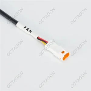
ODM Waterproof Series Harnesses IP68 Rated - Durable Solutions from China Suppliers and Factory for Various Applications Factories, Product
Explore Technical Specs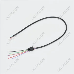
CE Certification High-Performance Equipment Cabinet Wiring Harness - Reliable Connectivity from China Suppliers & Factory Suppliers, Factories
Explore Technical Specs
Custom Waterproof Series Harnesses (IP68 Rating) - Reliable Solutions from China Suppliers and Factory for Various Applications Manufacturer, Factories
Explore Technical Specs
OEM Octagon SWP-7.5-G Air Booster Pump - Efficient China Suppliers & Factory for Enhanced Pressure Applications Factories, Service
Explore Technical Specs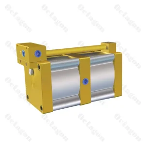
OEM OCTAGON SWP-02B Air Booster Pump: Quality Performance from Leading China Suppliers and Factory Manufacturers, Suppliers
Explore Technical SpecsEngineering Inquiry Parameters for Rapid RFQ Sizing
To accelerate fluid mechanics sizing, pressure pump selection, and cost estimation, our engineering group reviews five fundamental boundary parameters upon initial inquiry:
1. Pressure Regimes
Minimum and maximum plant drive air pressure (typically 3 to 8 bar), gas precharge inlet pressure, and the exact target discharge pressure (bar / psi).
2. Fluid Medium
Specific chemical media: clean dry air, nitrogen, helium, hydraulic oil, water-glycol, DI water, or specialized solvents to determine seal elastomer formulation.
3. Flow Demand
Required volumetric flow rate at continuous working pressure (L/min or standard m³/hr), distinguishing peak filling velocity from static holding phase.
4. Duty Profile
Intermittent cycling (burst testing or gate trim) vs. 24/7 continuous operation to select single-acting versus double-acting dual-drive architecture.
5. Interface Standards
Port configuration (NPT, BSPP, SAE O-ring boss, autoclave high-pressure coned fittings) and cabinet electrical control specifications (24VDC / 110VAC).
Frequently Answered Technical & Sourcing Questions
Authoritative answers directly from our senior fluid power engineers and tooling design specialists.
How does a pneumatic pressure booster pump achieve continuous pressure holding without burning out?
Unlike electric motors that overheat and draw massive locked-rotor current when forced to maintain static load, a pneumatic booster operates on pneumatic-hydraulic force balance. When fluid resistance downstream equals the intensified drive air force, the pump piston naturally comes to a complete physical halt (stall condition). In this stall state, no compressed air is consumed, no moving parts generate friction, and zero heat is produced. If downstream pressure drops slightly due to volume changes or micro-leakage, the pump immediately strokes automatically to restore pressure equilibrium.
What compressed air filtration quality is required upstream of the booster pump drive?
To ensure optimal valve shuttle response and seal longevity, drive air must conform to ISO 8573-1:2010 Class 4 for particles (filter rating ≤ 5 μm) and Class 4 for water vapor (pressure dew point ≤ +3°C). While modern Octagon pumps feature internally grease-packed seals capable of dry operation, installing a standard 5-micron particulate filter and moisture separator on the main supply line protects against abrasive pipe scale and liquid condensation.
Can Octagon pneumatic pumps handle pure deionized (DI) water or corrosive test fluids?
Yes. For pure DI water, food-contact liquids, or corrosive chemical flushing, we manufacture fluid-end wetted sections entirely from AISI 316L stainless steel, Hastelloy C-276, or titanium alloys. Wetted dynamic seals are customized using virgin PTFE or food-grade FKM, and check valves utilize ceramic balls to avoid galvanic corrosion and chemical leaching.
What is the fundamental difference between SWB-100S and SWB-100D booster series?
The suffix 'S' denotes a Single-Drive or Single-Acting mechanism, utilizing one reciprocating air piston to deliver fluid during the forward compression stroke. The suffix 'D' denotes a Double-Acting or Dual-Drive architecture, incorporating high-pressure plungers on both sides of the pneumatic drive cylinder. Double-acting models discharge fluid continuously on both strokes, reducing pressure ripple and providing almost double the volumetric flow at identical drive pressures.
How does an in-mold cutting automation cabinet interface with standard injection molding machines?
The high-pressure timing control cabinet interfaces with the injection press controller via standardized Euromap 67 / Euromap 12 or discrete 24VDC dry contacts. During the mold-fill cycle, the injection machine signals the control cabinet, which triggers pilot-operated pneumatic-hydraulic intensifiers to drive mold cutting cylinders (exerting 1,000 to 7,000 kgf) at the exact millisecond gate freeze occurs, cleanly removing runner gates prior to mold opening.
What lead times and spare parts availability can global customers expect?
Standard catalog models (SWB-80, SWB-100, SWP-7.5-G) and standard seal overhaul kits typically ship within 5 to 7 business days from our production facilities. Custom-engineered pneumatic packages, special ratio intensifiers, or bespoke control cabinets require 3 to 4 weeks for CAD/STEP drawing sign-off, machining, assembly, and 100% factory hydrostatic bench testing.
How are high-definition screen cables and IP68 wire harnesses integrated with pneumatic machinery?
Modern automated stamping and hydroforming presses require integrated electrical-pneumatic systems. Octagon manufactures both fluid power intensifiers and high-durability internal wiring harnesses (including IP68-rated waterproof connections and interference-shielded display cables) to deliver complete, interference-free control panels directly to machine builders without multi-vendor sourcing friction.
What documentation accompanies each export shipment for customs and plant safety audits?
Every shipment is accompanied by comprehensive engineering documentation, including the Certificate of Conformance (CoC), ISO 9001 factory inspection test reports (recording static holding pressure, drive stall pressure, and leak rates), Material Test Reports (MTRs compliant with EN 10204 3.1) for pressurized components, CE declaration of incorporation, and exploded CAD maintenance manuals with designated part numbers for rapid spare parts reordering.